
Build a Water Leak Detector
The Story
ESP32 Water Leak Detector solves a real beginner problem: turning an ESP32 reading into a useful physical or networked result. Build this to learn practical threshold sensing, corrosion limits, and how a small ESP32 circuit can prevent real damage.
The tutorial focuses on the engineering path: prove the input, understand the circuit, write readable code, then test the output under real conditions.
Explain Like I'm 12
The water sensor is like two metal rails on the floor. Dry rails are mostly disconnected. Water bridges them, current can pass through the module, and the ESP32 sees the change.
Safety Standards
- Unplug USB before changing jumper wires. Recheck 3.3 V, 5 V, and GND before reconnecting power.
- Do not power motors, pumps, LED strips, or servos from the ESP32 3.3 V pin. Use a suitable external supply and common ground.
- Breadboards are for low-current prototypes. Move high-current or unattended builds to proper terminals, enclosure, strain relief, and fusing.
- Motors and servos can reset the ESP32 when they draw surge current. Use a separate motor supply, driver module, and flyback protection where needed.
What You Will Build
A low-voltage ESP32 water leak alarm that reads a resistive water sensor strip through AOUT on GPIO34 and DOUT on GPIO35, sounds a buzzer on GPIO25, turns on a red leak LED on GPIO26, and keeps a green normal LED on GPIO27 when the sensor is dry.
Learning Objectives
- Detect water using analog and digital sensor outputs.
- Understand why resistive water probes corrode over time.
- Create a safe local buzzer/LED alarm.
- Choose sensor placement for real leaks.
- Prepare the project for future Wi-Fi alerts.
Components List
- 1× ESP32 DevKit V1Required for this build
- 1× Resistive water sensor stripParallel copper trace strip; inexpensive module
- 1× Active buzzer 5 VRequired for this build
- 1× Red LED and 220 ohm resistorLeak indicator
- 1× Green LED and 220 ohm resistorNormal status indicator
- 1× Breadboard and jumper wiresRequired for this build
- USB data cableProgramming and bench power
Bill of Materials
| Part | Qty | Estimated Cost | Notes |
|---|---|---|---|
| 1× ESP32 DevKit V1 | 1 | Varies | Required for this build |
| 1× Resistive water sensor strip | 1 | Varies | Parallel copper trace strip; inexpensive module |
| 1× Active buzzer 5 V | 1 | Varies | Required for this build |
| 1× Red LED and 220 ohm resistor | 1 | Varies | Leak indicator |
| 1× Green LED and 220 ohm resistor | 1 | Varies | Normal status indicator |
| 1× Breadboard and jumper wires | 1 set | Varies | Required for this build |
Wiring
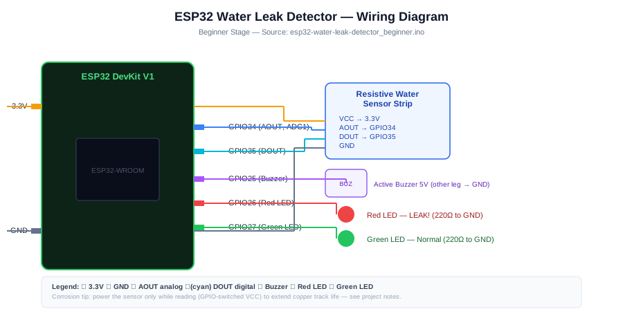
Wire the resistive water sensor strip first and confirm dry and wet readings in Serial Monitor. Then connect the buzzer and LEDs so the local alarm behavior is easy to test.
-
1
Unplug USB before changing wires.
-
2
Connect Water sensor AOUT to GPIO 34 (Analog signal; higher voltage = wetter).
-
3
Connect Water sensor DOUT to GPIO 35 (Digital threshold from onboard comparator).
-
4
Connect Water sensor VCC to 3.3 V for the beginner build; power the sensor only while reading in longer-term versions to reduce electrolytic corrosion.
-
5
Connect Water sensor GND to GND.
-
6
Connect Buzzer + to GPIO 25.
-
7
Connect Red LED anode to GPIO 26.
-
8
Connect Green LED anode to GPIO 27.
-
9
Reconnect USB, upload the sketch, and open Serial Monitor at 115200 baud unless the code says otherwise.
GPIO Mapping
| Signal | ESP32 Pin | Direction | Notes |
|---|---|---|---|
| Water sensor AOUT | GPIO 34 | Input | Analog signal; higher voltage = wetter |
| Water sensor DOUT | GPIO 35 | Input | Digital threshold from onboard comparator |
| Water sensor VCC | 3.3 V | Power | Beginner wiring uses 3.3 V; longer-term builds should switch sensor power only during readings. |
| Water sensor GND | GND | Ground | Match this wire to the code constant. |
| Buzzer + | GPIO 25 | Output | Match this wire to the code constant. |
| Red LED anode | GPIO 26 | Output | Match this wire to the code constant. |
| Green LED anode | GPIO 27 | Output | Match this wire to the code constant. |
Circuit Explanation
The water strip exposes conductive traces. When water touches the traces, resistance changes and the module output changes. The ESP32 can read the analog output for wetness level or digital output for simple leak/no-leak detection. LEDs and buzzer provide immediate local feedback.
Engineering Explanation
Water detection is simple electrically but tricky in real installations. Minerals in water, corrosion, condensation, sensor placement, and cable length affect reliability. A good detector powers the sensor only while reading, tests both wet and dry states, and places the probe where water appears first.
Libraries
- Arduino ESP32 coreInstall ESP32 board support in Arduino IDE.
Code
Copy into Arduino IDE. Install any libraries noted in the component guides first.
// ESP32 Water Leak Detector - Beginner
// Resistive moisture sensor; buzzer + LED alert

const int SENSOR_AOUT = 34;
const int SENSOR_DOUT = 35;
const int BUZZER  = 25;
const int LED_RED = 26;
const int LED_GRN = 27;

const int WET_THRESHOLD = 2000; // tune from Serial output; 0-4095

void setup() {
  Serial.begin(115200);
  analogReadResolution(12);
  pinMode(SENSOR_DOUT, INPUT);
  pinMode(BUZZER,  OUTPUT);
  pinMode(LED_RED, OUTPUT);
  pinMode(LED_GRN, OUTPUT);
}

void loop() {
  int raw = analogRead(SENSOR_AOUT);
  bool wet = (raw > WET_THRESHOLD) || (digitalRead(SENSOR_DOUT) == HIGH);

  Serial.printf("Sensor: %d  Status: %sn", raw, wet ? "WET!" : "dry");

  if (wet) {
    digitalWrite(LED_RED, HIGH);
    digitalWrite(LED_GRN, LOW);
    digitalWrite(BUZZER,  HIGH);
  } else {
    digitalWrite(LED_RED, LOW);
    digitalWrite(LED_GRN, HIGH);
    digitalWrite(BUZZER,  LOW);
  }
  delay(1000);
}
Code Explanation
The sketch starts Serial Monitor, defines readable pin constants, configures input and output pins in setup(), then repeats the measurement and decision logic in loop(). The loop prints the live reading first, compares it with a threshold, then changes the output. Printing before controlling the output makes debugging much easier because you can see what the ESP32 believes is happening.
Expected Output
Serial Monitor should print the raw sensor value and "dry" while the strip is clean and dry. When water bridges the copper traces and the reading rises above WET_THRESHOLD or DOUT goes HIGH, the red LED and buzzer should turn on while the green LED turns off.
Troubleshooting
- Alarm always stays on Dry the sensor completely, clean residue between traces, and record raw dry readings before raising WET_THRESHOLD.
- Alarm never triggers Touch the traces with a damp cloth and verify 3.3 V, GND, AOUT on GPIO34, DOUT on GPIO35, and the sensor module threshold potentiometer if present.
- False alarms happen overnight Move the sensor away from condensation sources or raise the threshold after logging dry readings.
- Sensor corrodes after repeated tests Use brief wet tests, dry the strip afterward, and switch sensor power only during readings for longer-term monitoring.
- Buzzer is weak Use an active buzzer module and check whether it needs 5 V or a transistor driver.
Common Mistakes
- Leaving a resistive water sensor powered continuously for months.
- Placing the sensor where water reaches it too late.
- Using the buzzer before proving the sensor reading works.
- Ignoring corrosion after repeated wet tests.
- Forgetting to dry the sensor completely before retesting.
Testing Checklist
- Upload a simple Blink sketch first to confirm the board and USB cable work.
- Wire only power and ground, then confirm the board still boots.
- Connect the input signal and print raw readings before using thresholds.
- Trigger the real-world condition slowly and watch Serial Monitor.
- Connect the output only after the input reading is believable.
- Power-cycle the project and confirm it starts in a safe state.
Engineering Tips
- Power the sensor only during measurement to reduce electrolysis.
- Keep the ESP32 board away from the wet area.
- Use a drip loop in cables so water cannot run toward electronics.
- Test with a damp cloth, not a cup of water near the board.
- Use a plastic enclosure for permanent monitoring.
Performance Tips
- Sleep between checks for battery operation.
- Use digital output for simple alarms and analog output for wetness trend.
- Require two wet readings before sounding the alarm.
- Send network alerts only when the state changes.
Upgrade Ideas
- Add Wi-Fi and send a push notification when leak is detected
- Add multiple sensors on different GPIO ADC pins for multi-zone detection
- Add a solenoid valve relay to cut main water supply automatically
- Add an OLED showing which zone is wet and for how long
Real-World Applications
- Sink cabinet leak alarm
- Water heater drip monitor
- Basement early warning sensor
- Appliance overflow detector
Downloads
- ESP32 Water Leak Detector Arduino sketchUse the code section as the source sketch.
- Bench test checklistFollow the testing checklist before permanent installation.
FAQs
Can the sensor detect tiny droplets?
Only if the droplets bridge the sensor traces enough to change the reading. Test with small amounts of water before trusting a placement.
Where should I place the leak sensor?
Put it where water would reach early, such as the lowest point near a pipe, tray, or appliance base. A sensor placed too high may trigger too late.
What happens after the sensor dries?
The reading should fall back below the alarm threshold, but corrosion or residue can cause false alarms. Clean and dry the strip after wet tests.
Review, Testing, and References
Author: Abdul Mubeen and the ESP32 Engine editorial team. Last updated: 2026-08-22. Reviewed: wiring logic, Arduino code structure, beginner safety, and learning sequence.
Educational level: Beginner. Estimated completion time: 50-80 min. This project is for learning and prototyping; production or unattended hardware needs additional engineering review.
Project Complete!
You completed ESP32 Water Leak Detector as a real ESP32 engineering build, not just a wiring demo. You now know how to test the input, protect the circuit, explain the code, and improve the project safely.
- Read and verify project input hardware
- Map signals to safe ESP32 GPIO pins
- Debug with Serial Monitor
- Apply safety and performance checks
- Plan the next learning step