
The Story
A normal digital output is simple: ON or OFF. PWM is what you use when a project needs something that feels adjustable, such as dim LED light, RGB color mixing, or a speed command sent to a motor driver.
Background reading
ESP32 PWM lets a digital GPIO create smooth-looking LED brightness, motor-driver speed commands, buzzer tones, and other adjustable outputs. This guide explains PWM from first principles, then shows the current Arduino IDE pattern for changing duty cycle safely.
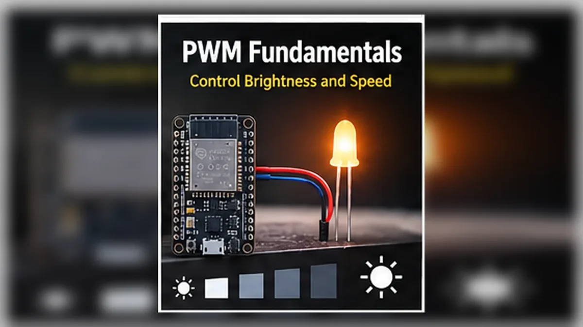
A normal digital output is simple: ON or OFF. PWM is what you use when a project needs something that feels adjustable, such as dim LED light, RGB color mixing, or a speed command sent to a motor driver.
PWM means the ESP32 switches a pin ON and OFF very quickly. More ON time looks brighter. Less ON time looks dimmer. The pin is still digital, but the average effect becomes useful.
Author: Abdul Mubeen and the ESP32 Engine editorial team. Last updated: 2026-09-23. Reviewed: educational accuracy and beginner safety. Level: Beginner. Estimated time: 18 min read.
This guide is written for learning and bench prototyping. Check the testing notes before adapting the circuit to different boards, batteries, relays, motors, or outdoor hardware.
PWM stands for Pulse Width Modulation. A pulse is the ON part of a digital signal. Width means how long that ON part lasts. Modulation means changing it.
An ESP32 GPIO pin normally has two simple output states: LOW and HIGH. PWM still uses those same two states, but repeats them quickly. If the pin is ON for most of each cycle, an LED looks bright. If the pin is ON for only a small part of each cycle, the LED looks dim.
That is the key idea: PWM does not create a true adjustable analog voltage on a GPIO pin. It creates an adjustable average effect by switching fast.
| Output style | What the pin does | Beginner example |
|---|---|---|
| Digital LOW | Stays near 0 V. | LED off. |
| Digital HIGH | Stays near 3.3 V. | LED full brightness. |
| PWM | Switches LOW/HIGH repeatedly. | LED appears dim, medium, or bright depending on duty cycle. |
If you have not uploaded code yet, start with the ESP32 Arduino IDE guide. If you have never controlled a GPIO output, build Blink an LED with ESP32 first.
PWM frequency is how many complete ON/OFF cycles happen each second. A frequency of 5000 Hz means 5000 PWM cycles per second. LED dimming usually uses a frequency high enough that your eyes do not see obvious blinking. Buzzers, motor drivers, servos, and LEDs may need different frequency ranges, so match the load instead of assuming one value fits everything.
Duty cycle is the ON-time portion of each cycle. A 25% duty cycle is ON for one quarter of the cycle and OFF for the rest. A 75% duty cycle is ON for most of the cycle. For an LED, higher duty usually looks brighter.
Resolution controls how many duty steps are available. With 8-bit resolution, duty can range from 0 to 255. With 10-bit resolution, duty can range from 0 to 1023. More resolution gives finer brightness steps, but very high frequency and high resolution compete for timing resources.
The ESP32 LEDC peripheral uses PWM channels/timers internally. Older Arduino-ESP32 examples made you choose channel numbers manually. Current Arduino-ESP32 examples can attach PWM directly to a pin with ledcAttach(pin, frequency, resolution), and then write duty with ledcWrite(pin, duty). The underlying channel idea still matters when you run many PWM outputs, but beginners usually start with one pin.
Many output-capable ESP32 GPIO pins can generate LEDC PWM. For a first LED brightness example, use a common output-capable pin such as GPIO18. Avoid these beginner mistakes:
This guide uses an LED because it makes PWM visible immediately. Wire it as a low-current learning circuit:
The resistor is required. PWM changes average brightness, but when the pin is ON, the LED still needs current limiting.
Current Arduino-ESP32 cores support the pin-based LEDC helpers shown below. This keeps the beginner sketch clear: attach PWM to a pin, then write duty values to that same pin.
const int PWM_PIN = 18;
  const int PWM_FREQUENCY = 5000;
  const int PWM_RESOLUTION = 8;
  const int DUTY_MAX = (1 << PWM_RESOLUTION) - 1;

  void setup() {
    Serial.begin(115200);

    bool attached = ledcAttach(PWM_PIN, PWM_FREQUENCY, PWM_RESOLUTION);
    if (!attached) {
      Serial.println("PWM attach failed. Check board selection and pin.");
      while (true) {
        delay(1000);
      }
    }

    Serial.println("ESP32 PWM fade ready");
  }

  void loop() {
    for (int duty = 0; duty <= DUTY_MAX; duty += 5) {
      ledcWrite(PWM_PIN, duty);
      Serial.print("Duty: ");
      Serial.println(duty);
      delay(20);
    }

    for (int duty = DUTY_MAX; duty >= 0; duty -= 5) {
      ledcWrite(PWM_PIN, duty);
      Serial.print("Duty: ");
      Serial.println(duty);
      delay(20);
    }
  }
Expected behavior: the LED fades from off to bright, then bright to off. Serial Monitor prints changing duty values from 0 toward 255 and back down because this example uses 8-bit resolution.
With 8-bit resolution, these fixed duty values are easy to understand:
| Duty value | Approximate duty cycle | LED effect |
|---|---|---|
0 | 0% | Off |
64 | 25% | Dim |
128 | 50% | Medium |
192 | 75% | Bright |
255 | 100% | Full brightness |
To hold one brightness level, call ledcWrite(PWM_PIN, 128) in your code. To build a dimmer, change the duty value when a button event, analog reading, or web command changes.
Frequency and resolution are connected. A very high PWM frequency leaves less timing room for very fine duty steps. A very high resolution gives more duty steps, but may limit how high the frequency can be. For beginner LED dimming, 5000 Hz and 8-bit resolution are a practical starting point.
If an LED flickers, try a higher frequency or check for loose wiring. If brightness jumps feel coarse, try more resolution or smaller duty changes. If a motor driver behaves strangely, read that driver module's documentation before changing random PWM values.
You will still see older tutorials using code like this:
ledcSetup(channel, frequency, resolution);
  ledcAttachPin(pin, channel);
  ledcWrite(channel, duty);
That style is common in older Arduino-ESP32 core examples and in some existing learning material. For new code on current Arduino-ESP32 cores, prefer the pin-based style:
ledcAttach(pin, frequency, resolution);
  ledcWrite(pin, duty);
If old code fails with an error such as ledcAttachPin was not declared, check your installed ESP32 board package version and update the PWM API style.
| Problem | Likely cause | Fix |
|---|---|---|
| LED never turns on | Wrong GPIO, reversed LED, missing ground, or resistor not in series. | Use GPIO18, check LED polarity, and trace GPIO18 -> resistor -> LED -> GND. |
| LED is always full bright | LED may be wired to 3.3 V instead of the PWM pin. | Move the circuit so GPIO18 drives the resistor/LED path. |
| Compile error for ledcAttach | Wrong board selected or older ESP32 board package. | Select an ESP32 board in Arduino IDE and update the ESP32 board package if needed. |
| Compile error for ledcSetup or ledcAttachPin | Old channel-based code on a newer Arduino-ESP32 core. | Convert to ledcAttach(pin, freq, resolution) and ledcWrite(pin, duty). |
| Visible flicker | Low frequency, slow duty changes, weak connection, or unsuitable load. | Return to 5000 Hz for the LED example and inspect wiring. |
| Motor does not respond | GPIO connected directly to motor or no shared ground with driver. | Use a motor driver with separate motor power and common ground. |
Use the idea here in real ESP32 Engine builds:
PWM means Pulse Width Modulation. The ESP32 switches a GPIO ON and OFF quickly and changes the ON-time percentage, called duty cycle, to create an adjustable average effect.
Many output-capable ESP32 GPIO pins can generate PWM through the LEDC peripheral. Avoid input-only pins such as GPIO34-GPIO39 on classic ESP32 boards, flash pins, and boot-sensitive pins unless you understand the board.
A PWM channel is a hardware timing resource used by the ESP32 LEDC peripheral. Current Arduino-ESP32 APIs can allocate this for you when you attach a pin, while older examples often selected channel numbers manually.
5000 Hz is a practical beginner value for LED dimming in Arduino examples. Other loads may need different frequencies.
Duty cycle is the percentage of each PWM cycle that the signal is ON. Higher duty cycle sends more average energy to the load.
No. The GPIO still switches between digital LOW and HIGH. PWM creates an analog-like average effect through fast switching.
No. Use PWM as a control signal into a motor driver, MOSFET circuit, or suitable module. Do not connect a motor directly to a GPIO pin.
For current Arduino-ESP32 cores, prefer ledcAttach(pin, frequency, resolution) and ledcWrite(pin, duty). Older tutorials may use ledcSetup, ledcAttachPin, and channel-based ledcWrite as legacy API context.
ESP32 PWM is fast digital switching with a controlled duty cycle. Use duty cycle to change average output energy, choose frequency based on the load, choose resolution based on the duty steps you need, and use output-capable GPIO pins with suitable external drivers for anything larger than a small LED. Start with LED brightness, then apply the same idea to RGB projects, motor drivers, buzzers, and automation outputs.