
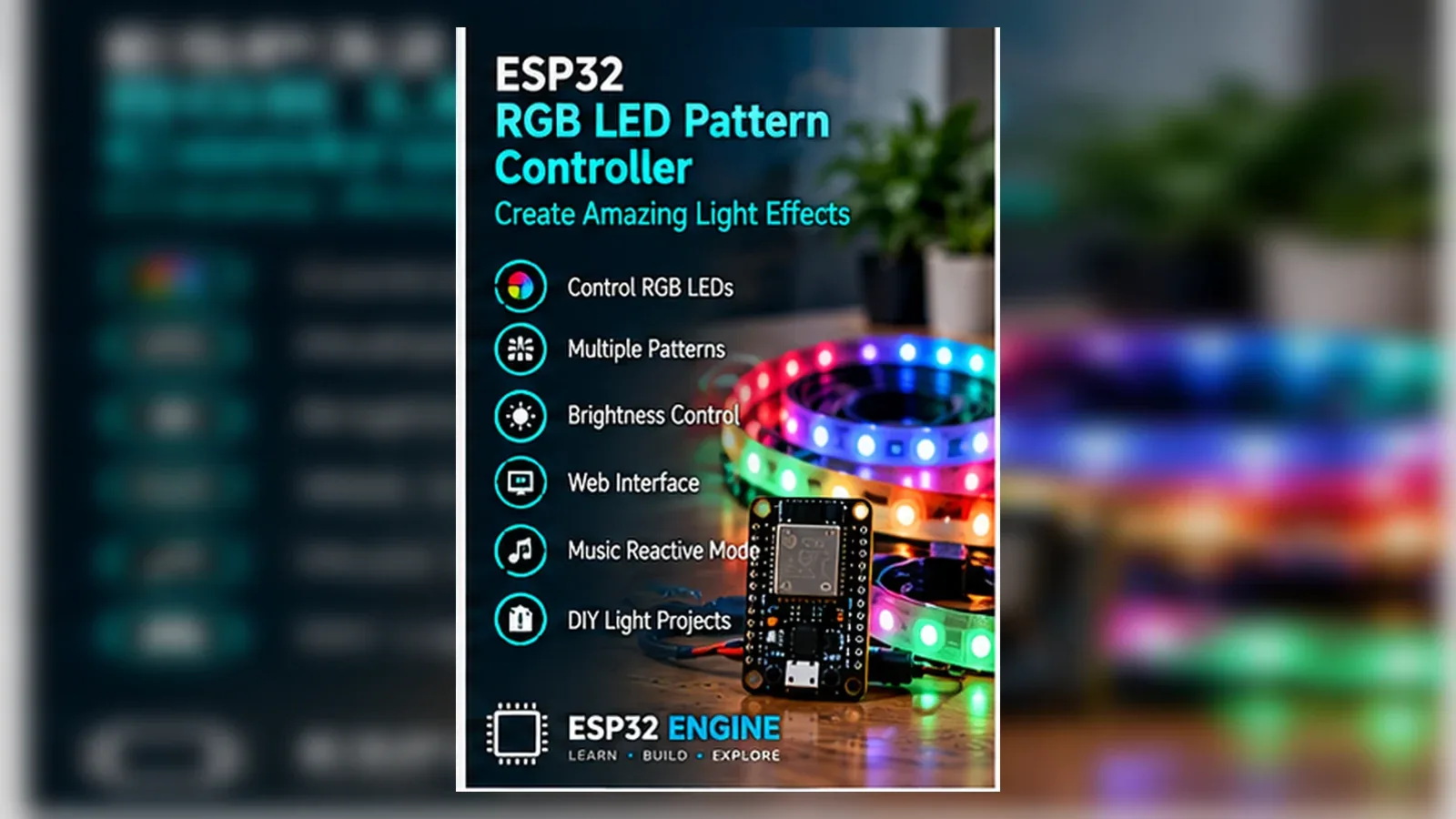
Build a Single RGB LED Pattern Controller
The Story
This project is intentionally a small PWM lesson, not a strip controller. The LED type, wiring polarity, and code all match common-cathode behavior.
Explain Like I'm 12
The RGB LED has red, green, and blue lights inside it. The ESP32 dims each one very quickly to mix colors.
Learning Support
- Recommended ageAges 10+
- Adult supervisionLow supervision; verify each LED channel has a resistor.
- Classroom useUse it for additive color and debouncing lessons.
- Parent promptAsk what color appears when red and green PWM are both high.
- Screen-free activityPredict colors for R/G/B duty-cycle combinations before testing.
- Next challengeAdd a second button for adjustable fade speed.
- Skills practiced
- PWM
- Button debouncing
- State machines
- Additive color
- Learning outcomes
- Wire a common-cathode RGB LED.
- Use LEDC PWM on GPIO25/GPIO26/GPIO27.
- Debounce a button on GPIO14.
- Differentiate a single RGB LED from addressable NeoPixels.
- Mini experiments
- Change PWM frequency.
- Create a fourth custom pattern.
- Swap the button for a potentiometer in a future build.
Safety Standards
- Unplug USB before changing jumper wires. Recheck 3.3 V, 5 V, and GND before reconnecting power.
- Do not power motors, pumps, LED strips, or servos from the ESP32 3.3 V pin. Use a suitable external supply and common ground.
- Breadboards are for low-current prototypes. Move high-current or unattended builds to proper terminals, enclosure, strain relief, and fusing.
What You Will Build
A single common-cathode RGB LED pattern controller using three PWM channels and one button.
Learning Objectives
- Wire a common-cathode RGB LED.
- Use LEDC PWM on GPIO25/GPIO26/GPIO27.
- Debounce a button on GPIO14.
- Differentiate a single RGB LED from addressable NeoPixels.
Components List
- ESP32 DevKit boardMain 3.3 V logic controller.
- Common-cathode 4-pin RGB LEDShared cathode goes to GND.
- Three 220 ohm resistorsOne per red, green, and blue channel.
- Push buttonPattern select input to GND using INPUT_PULLUP.
- Breadboard and jumper wiresFor low-voltage prototyping.
Bill of Materials
| Part | Qty | Estimated Cost | Notes |
|---|---|---|---|
| ESP32 DevKit board | 1 | Varies | Main 3.3 V logic controller. |
| Common-cathode 4-pin RGB LED | 1 | Varies | Shared cathode goes to GND. |
| Three 220 ohm resistors | 1 | Varies | One per red, green, and blue channel. |
| Push button | 1 | Varies | Pattern select input to GND using INPUT_PULLUP. |
| Breadboard and jumper wires | 1 | Varies | For low-voltage prototyping. |
Wiring
Common cathode goes to GND. Red, green, and blue anodes go through resistors to GPIO25, GPIO26, and GPIO27. Button connects GPIO14 to GND.
-
1
Unplug USB before wiring.
-
2
Connect the common cathode pin to GND.
-
3
Connect red through 220 ohm resistor to GPIO25.
-
4
Connect green through 220 ohm resistor to GPIO26.
-
5
Connect blue through 220 ohm resistor to GPIO27.
-
6
Connect one side of the button to GPIO14 and the other to GND.
GPIO Mapping
| Signal | ESP32 Pin | Direction | Notes |
|---|---|---|---|
| RGB red anode | GPIO25 | PWM output | Series resistor required. |
| RGB green anode | GPIO26 | PWM output | Series resistor required. |
| RGB blue anode | GPIO27 | PWM output | Series resistor required. |
| Pattern button | GPIO14 | Input | INPUT_PULLUP; button to GND. |
Circuit Explanation
Each color channel is a separate LED controlled by PWM. The button advances a pattern variable without delay-based blocking.
Engineering Explanation
Common-cathode means higher PWM duty makes the selected color brighter. Common-anode LEDs need inverted PWM and are not used here.
Libraries
- Arduino ESP32 coreUses built-in LEDC PWM functions only.
Code
Copy into Arduino IDE. Install any libraries noted in the component guides first.
// ESP32 common-cathode RGB LED pattern controller
// Single low-power RGB LED, not an addressable strip.
const int RED_PIN = 25;
const int GREEN_PIN = 26;
const int BLUE_PIN = 27;
const int BUTTON_PIN = 14;

const int RED_CH = 0;
const int GREEN_CH = 1;
const int BLUE_CH = 2;
const int PWM_FREQ = 5000;
const int PWM_RES = 8;

int pattern = 0;
bool lastButton = HIGH;
unsigned long lastDebounceMs = 0;
unsigned long frameMs = 0;

void writeRgb(uint8_t r, uint8_t g, uint8_t b) {
  ledcWrite(RED_CH, r);
  ledcWrite(GREEN_CH, g);
  ledcWrite(BLUE_CH, b);
}

void setupPwm() {
  ledcSetup(RED_CH, PWM_FREQ, PWM_RES);
  ledcSetup(GREEN_CH, PWM_FREQ, PWM_RES);
  ledcSetup(BLUE_CH, PWM_FREQ, PWM_RES);
  ledcAttachPin(RED_PIN, RED_CH);
  ledcAttachPin(GREEN_PIN, GREEN_CH);
  ledcAttachPin(BLUE_PIN, BLUE_CH);
}

void setup() {
  Serial.begin(115200);
  setupPwm();
  pinMode(BUTTON_PIN, INPUT_PULLUP);
  writeRgb(255, 0, 0);
}

void loop() {
  bool button = digitalRead(BUTTON_PIN);
  if (button != lastButton && millis() - lastDebounceMs > 40) {
    lastDebounceMs = millis();
    lastButton = button;
    if (button == LOW) {
      pattern = (pattern + 1) % 3;
      Serial.printf("Pattern %d\n", pattern);
    }
  }

  unsigned long now = millis();
  if (now - frameMs < 20) return;
  frameMs = now;

  uint8_t phase = (now / 8) & 0xFF;
  if (pattern == 0) {
    writeRgb(255, 0, 0);
  } else if (pattern == 1) {
    writeRgb(phase, 255 - phase, 128);
  } else {
    int step = (now / 500) % 6;
    const uint8_t colors[6][3] = {{255,0,0},{255,80,0},{0,255,0},{0,255,255},{0,0,255},{160,0,255}};
    writeRgb(colors[step][0], colors[step][1], colors[step][2]);
  }
}
Code Explanation
Three LEDC channels drive RGB pins. The button is debounced with millis() and advances a non-blocking pattern state.
Expected Output
The RGB LED changes pattern on each button press without long pauses or double-triggering.
Troubleshooting
- Colors are inverted You may have a common-anode LED; use common-cathode or invert PWM.
- One color is missing Check that channel's resistor and LED pin.
- Button double-triggers Increase debounce time or check wiring.
Common Mistakes
- Using a common-anode LED without changing logic.
- Skipping resistors.
- Expecting this to control a NeoPixel strip.
- Using delay() for debounce.
Testing Checklist
- Test each color channel individually.
- Press button ten times and watch for missed or double steps.
- Confirm fades continue while button is idle.
Engineering Tips
- Identify the longest LED leg before wiring.
- Use one resistor per channel.
- Keep the button wiring short.
Upgrade Ideas
- Add adjustable fade speed.
- Add a potentiometer color mixer.
- Save last pattern in preferences.
Real-World Applications
- Additive color lesson
- PWM demonstration
- Button state-machine exercise
FAQs
Is this for NeoPixels?
No. It is one common-cathode RGB LED.
Why three resistors?
Each color channel needs its own current limit.
What if my LED is common-anode?
Use a common-cathode LED for this tutorial or invert the PWM logic.
Review, Testing, and References
Author: Abdul Mubeen and the ESP32 Engine editorial team. Last updated: 2026-06-18. Reviewed: wiring logic, Arduino code structure, beginner safety, and learning sequence.
Educational level: Beginner. Estimated completion time: 45-60 min. This project is for learning and prototyping; production or unattended hardware needs additional engineering review.
Project Complete!
You completed ESP32 RGB LED Pattern Controller with matching wiring, code, tests, and limitations.
- PWM
- Button debouncing
- State machines