
The Story
A push button is one of the simplest ways to let a project listen to a person. The small trick is giving the GPIO a known resting state, then translating the electrical HIGH and LOW into the everyday meanings released and pressed.
Background reading
Connect a push button between a suitable ESP32 GPIO and GND, then use INPUT_PULLUP to get a stable released state. This guide explains the wiring, HIGH/LOW logic, a complete debounce sketch, and the board-specific pin details to check.
A push button is one of the simplest ways to let a project listen to a person. The small trick is giving the GPIO a known resting state, then translating the electrical HIGH and LOW into the everyday meanings released and pressed.
A GPIO input is like a tiny listener that can report HIGH or LOW. A button changes the signal, and a pull-up resistor makes sure the signal does not wander when nobody is pressing it.
Author: Abdul Mubeen and the ESP32 Engine editorial team. Last updated: 2026-10-03. Reviewed: educational accuracy and beginner safety. Level: Beginner. Estimated time: 10 min read.
This guide is written for learning and bench prototyping. Check the testing notes before adapting the circuit to different boards, batteries, relays, motors, or outdoor hardware.
A GPIO is a general-purpose input/output pin. In input mode, the ESP32 samples the voltage on the pin and reports a digital state: HIGH when the signal is interpreted as a logic-high voltage and LOW when it is interpreted as logic-low. The input is not measuring a precise voltage like an analog input; it answers a yes-or-no question.
A bare input wire that is not connected to a definite high or low signal can float. Electrical noise and nearby wires may then push its reading back and forth. A pull-up gently biases the input HIGH; a pull-down gently biases it LOW. These resistors provide a quiet default without preventing a button from changing the state.
On GPIOs supported by the selected ESP32 board and Arduino core, pinMode(pin, INPUT_PULLUP) enables a weak internal resistor that biases an open input HIGH; a button from GPIO to GND then reads HIGH when released and LOW when pressed. The opposite arrangement uses pinMode(pin, INPUT_PULLDOWN): the internal resistor biases the open input LOW, and the button connects GPIO to 3.3 V, so released reads LOW and pressed reads HIGH. These are alternate circuits; use the wiring and active logic that match the selected mode.
Internal pulls are not available on every pin or board. For example, classic ESP32 GPIO34–GPIO39 are input-only and have no internal pull-up or pull-down; check the selected board/core documentation and use an external bias resistor when needed. This guide's complete sketch uses the pull-up pattern.
pinMode(BUTTON_PIN, INPUT_PULLDOWN);  // only on a pin/core that supports it
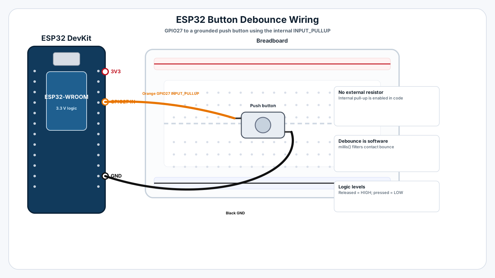
bool pressed = (digitalRead(BUTTON_PIN) == HIGH); // button connects GPIO to 3.3 VThis example uses GPIO27 on a common original ESP32 DevKit. Connect one button terminal to GPIO27 and the opposite terminal to GND. In code, INPUT_PULLUP enables the GPIO's internal pull-up, so a separate resistor is not normally needed for this simple circuit.
| Button connection | ESP32 example | Notes |
|---|---|---|
| One terminal | GPIO27 | Example input pin; confirm your board pinout and update the code if needed. |
| Opposite terminal | GND | Pressing the button connects GPIO27 to ground. |
| Power / resistor | None for this circuit | INPUT_PULLUP supplies the internal bias; do not connect 3.3 V to the button in this wiring pattern. |
With INPUT_PULLUP, logic is intentionally inverted from a common first guess:
Small tactile switches often have pairs of internally connected legs. Orient a four-leg switch across the breadboard's center gap so pressing it joins the two sides. Package layouts vary: if unsure, use the switch datasheet or continuity mode on a multimeter to identify which terminals connect only when pressed.
GPIO27 is a convenient example on many original ESP32 DevKit boards, but ESP32-C3, S2, S3, and other boards do not share an identical pinout. Check the documentation for your exact board before wiring. Some pins have boot-strapping roles; on the classic ESP32, GPIO0, GPIO2, GPIO5, GPIO12, and GPIO15 are strapping pins whose level during reset can affect boot behavior. Avoid using such a pin for a beginner button unless you understand the board's constraints.
On the classic ESP32, GPIO34–GPIO39 are input-only and do not provide the internal pull-up/pull-down resistors. A button circuit using one of these pins needs an external bias resistor instead of relying on INPUT_PULLUP. Capabilities differ across chip families, so do not copy that pin rule blindly to every ESP32 variant.
No extra sensor or button library is required. In Arduino IDE, select the correct ESP32 board and port, then upload this sketch. It reports only stable transitions, so the Serial Monitor does not print a stream of duplicate events while the button is held.
const int BUTTON_PIN = 27;  // GPIO27 on a common original ESP32 DevKit
  const unsigned long DEBOUNCE_MS = 35;

  int lastRawState = HIGH;
  int stableButtonState = HIGH;
  unsigned long lastChangeTime = 0;

  void setup() {
    Serial.begin(115200);
    pinMode(BUTTON_PIN, INPUT_PULLUP);
    Serial.println("Button ready. Press the button to test.");
    Serial.println("Released = HIGH; pressed = LOW.");
  }

  void loop() {
    int rawState = digitalRead(BUTTON_PIN);

    if (rawState != lastRawState) {
      lastRawState = rawState;
      lastChangeTime = millis();
    }

    if ((millis() - lastChangeTime) >= DEBOUNCE_MS &&
        rawState != stableButtonState) {
      stableButtonState = rawState;

      if (stableButtonState == LOW) {
        Serial.println("Button pressed");
      } else {
        Serial.println("Button released");
      }
    }
}BUTTON_PIN keeps the selected input in one place. If your wiring uses another suitable pin, change this constant to match.pinMode(BUTTON_PIN, INPUT_PULLUP) makes the pin an input and enables its internal weak pull-up.digitalRead() returns HIGH for the released button and LOW while it connects the GPIO to GND.lastRawState tracks the latest electrical sample. Each raw transition restarts the debounce timer.stableButtonState changes only after the raw reading has stayed unchanged for DEBOUNCE_MS.millis() keeps checking without pausing the whole program with delay(). A 35 ms debounce interval is a practical starting value, not a universal value for every switch.Upload the sketch, open Serial Monitor, and set its baud rate to 115200. The initial message explains the active-low logic. Each clean press should print one Button pressed line; releasing it should print one Button released line. Holding the button should not generate repeated messages.
The input may be floating, or the pull-up is not enabled. Confirm INPUT_PULLUP, use a GPIO that supports an internal pull-up on your board, and check for a loose jumper.
For this button-to-GND INPUT_PULLUP circuit, LOW means pressed and HIGH means released. Reverse the software test only if your wiring intentionally uses a different bias arrangement.
Confirm the code pin matches the wire. Check that the other button terminal reaches ESP32 GND and that the legs are not placed in the same breadboard-connected group. Rotate a four-leg tactile switch or move it across the breadboard center trench.
Move the button to a suitable non-strapping pin recommended by your board documentation. Some GPIOs affect boot mode when held at reset, and available pins vary by ESP32 family and board.
On the classic ESP32, GPIO34–GPIO39 are input-only and lack internal pull resistors. Choose another suitable GPIO or add a correctly wired external pull-up; check the exact ESP32 variant's datasheet.
Set the monitor baud rate to 115200 to match Serial.begin(115200), and select the correct serial port after upload.
For the basic circuit controlling an LED, continue to Button Controls LED with ESP32. To understand the electrical default state, read Pull-Up vs Pull-Down Resistors and Understanding Digital Inputs and Floating Pins. The dedicated Button Debouncing lesson goes deeper into timing and press counting. Then try Multiple Buttons and State Detection, explore the ESP32 RGB LED Pattern Controller project, or begin with Blink LED with ESP32 before extending the input circuit.
The internal pull-up weakly biases the input toward the logic supply. When the button is open, the input reads HIGH; pressing connects it to ground and reads LOW.
Usually not for a GPIO with a working internal pull-up and a short button wire. Some pins lack internal pulls, and a long or noisy wire may need a circuit designed for that environment.
GPIO27 is the example for a common original ESP32 DevKit. Check your board's pinout and avoid pins with boot or peripheral constraints you have not accounted for.
A mechanical switch can bounce briefly between electrical states. The debounce timer waits for a stable reading before printing the transition.
An un-biased input can float and respond to electrical noise. Enable a supported internal pull-up/down or add a correctly wired external resistor.
The internal pull-up weakly connects the input to the ESP32 logic supply, so the open button rests at HIGH. Pressing the button connects the input to GND, making it LOW.
For this simple button-to-GND circuit, the internal pull-up provides the bias resistor, so a separate pull-up is usually unnecessary. Some GPIOs or board variants may not provide the requested internal pull-up; check the exact board documentation.
GPIO27 is used here as an example on a common original ESP32 DevKit. GPIO availability and boot-strapping behavior vary across ESP32 families and boards, so verify the exact pinout before choosing a pin.
Mechanical contacts can rapidly switch between open and closed for a short time when pressed or released. Debouncing waits for the reading to stay stable before reporting a state change.
The GPIO may be floating because no pull-up or pull-down sets its idle state. Enable INPUT_PULLUP with the button connected to GND, or use a correctly wired external bias resistor.
Start with a button between a suitable GPIO and GND, enable INPUT_PULLUP, and interpret LOW as pressed. The millis()-based debounce example turns noisy mechanical transitions into one stable state change. Once it works in Serial Monitor, continue to the pull-up, floating-pin, debouncing, and button-controlled LED lessons.