
Build an RFID Inventory Tracker
The Story
Inventory systems work because every scan becomes a reliable event. RC522 and SD share the SPI bus, while GPIO5 and GPIO4 keep separate chip-select signals so the ESP32 can talk to one module at a time. The component list, wiring table, GPIO map, code constants, expected output, troubleshooting, and FAQ now describe the same bench build so a learner can verify each step instead of guessing.
Explain Like I'm 12
An RFID tag has a small ID number. The reader asks for that number, the ESP32 checks the known list, writes a line to the memory card, and flashes the matching LED. Prove the local wiring and code first, then add displays, logging, or Wi-Fi after the simple version behaves exactly as expected.
Safety Standards
- Unplug USB before changing jumper wires. Recheck 3.3 V, 5 V, and GND before reconnecting power.
- Do not power motors, pumps, LED strips, or servos from the ESP32 3.3 V pin. Use a suitable external supply and common ground.
- Breadboards are for low-current prototypes. Move high-current or unattended builds to proper terminals, enclosure, strain relief, and fusing.
- Li-ion battery builds need a protected cell, proper charger, fuse, and enclosure. Never charge unknown or damaged cells.
What You Will Build
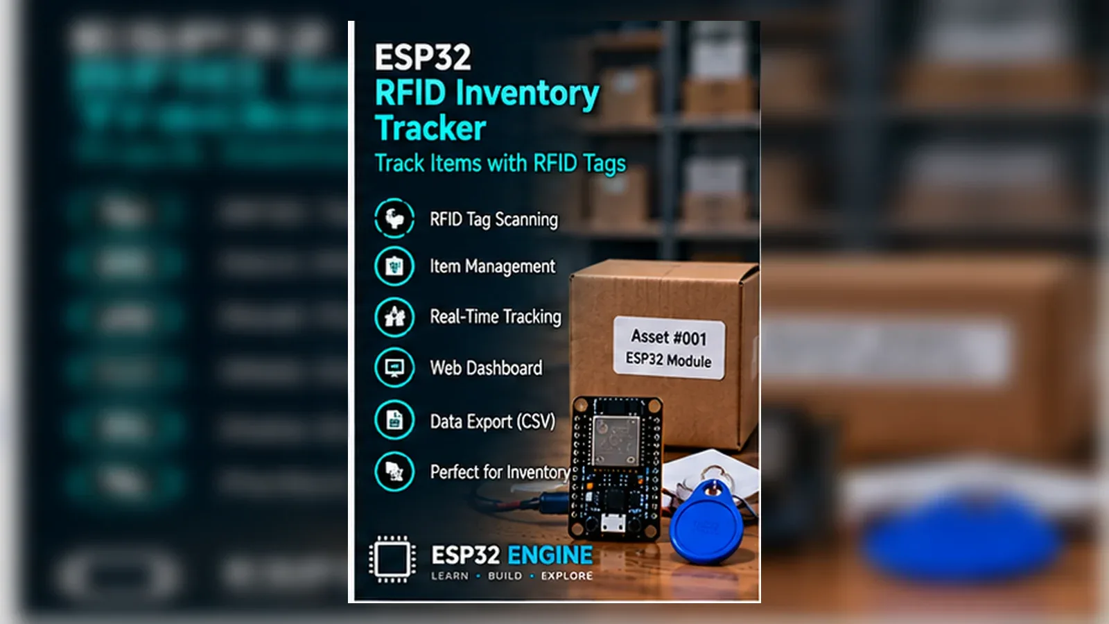
An ESP32 DevKit inventory logger that scans MIFARE-compatible tags with an RC522 RFID reader over SPI, maps known UID strings to asset names in the sketch, appends each scan to a microSD CSV file, and flashes green or red LEDs for known or unknown tags. The beginner build is local SD logging, not a live database or cloud inventory system.
Learning Objectives
- Wire the exact GPIO pins used by the sketch.
- Run the starter code and compare output with the wiring table.
- Explain the main sensor or input signal in plain language.
- Troubleshoot one wiring mistake using Serial Monitor evidence.
Components List
- ESP32 DevKit boardControls SPI, LEDs, and logging.
- RC522 RFID reader module13.56 MHz RFID reader powered from 3.3 V.
- MIFARE-compatible RFID cards or tagsUse test tags for the known UID list.
- MicroSD card moduleSPI storage with CS on GPIO4.
- Green and red LEDs with series resistorsKnown and unknown feedback on GPIO26 and GPIO27.
Bill of Materials
| Part | Qty | Estimated Cost | Notes |
|---|---|---|---|
| ESP32 DevKit board | 1 | Varies | Controls SPI, LEDs, and logging. |
| RC522 RFID reader module | 1 | Varies | 13.56 MHz RFID reader powered from 3.3 V. |
| MIFARE-compatible RFID cards or tags | 1 | Varies | Use test tags for the known UID list. |
| MicroSD card module | 1 | Varies | SPI storage with CS on GPIO4. |
| Green and red LEDs with series resistors | 1 | Varies | Known and unknown feedback on GPIO26 and GPIO27. |
Wiring
An RFID tracker that scans RC522 tags over SPI, logs events to a microSD card, and uses red and green LEDs for known or unknown tags.
-
1
Unplug USB before changing SPI, LED, or SD wiring.
-
2
Connect RC522 SDA/SS to GPIO5, SCK to GPIO18, MOSI to GPIO23, MISO to GPIO19, and RST to GPIO22.
-
3
Connect RC522 3.3 V and GND to the ESP32 3.3 V and GND rails.
-
4
Connect SD CS to GPIO4 while sharing SCK, MOSI, and MISO with SPI.
-
5
Connect green LED through its resistor to GPIO26 and red LED through its resistor to GPIO27.
-
6
Reconnect USB and test one RFID tag before relying on the SD log.
GPIO Mapping
| Signal | ESP32 Pin | Direction | Notes |
|---|---|---|---|
| RC522 SDA/SS | GPIO5 | Output | RC522 chip select. |
| SPI SCK/MOSI/MISO | GPIO18 / GPIO23 / GPIO19 | I/O | Shared SPI bus. |
| RC522 RST | GPIO22 | Output | RFID reset. |
| SD CS | GPIO4 | Output | Separate SD chip select. |
| Green LED / Red LED | GPIO26 / GPIO27 | Output | Scan feedback. |
Circuit Explanation
RC522 and SD share SCK, MOSI, and MISO. Separate chip-select pins prevent both modules from answering at once.
Engineering Explanation
SPI sharing works only when chip-select wiring and code agree. The RC522 is powered from 3.3 V in this tutorial. UID matching is useful for a classroom prototype, but UID-only RFID is not cryptographic security and does not prove ownership or prevent cloned tags.
Libraries
- Arduino ESP32 coreInstall ESP32 board support in Arduino IDE.
Code
Copy into Arduino IDE. Install any libraries noted in the component guides first.
// ESP32 RFID Inventory Tracker - Beginner
// RC522 tag scan -> SD card CSV log with known/unknown LED feedback
// Libraries: MFRC522 by GithubCommunity, SD by Arduino

#include <SPI.h>
#include <MFRC522.h>
#include <SD.h>

#define RC522_SS  5
#define RC522_RST 22
#define SD_CS     4
#define LED_GREEN 26
#define LED_RED   27

MFRC522 rfid(RC522_SS, RC522_RST);

// Known tag UIDs (hex strings) mapped to asset names
const char* KNOWN_UIDS[] = {"A1B2C3D4", "11223344", "DEADBEEF"};
const char* ASSET_NAMES[] = {"Laptop-01", "Camera-01", "Toolbox-01"};
const int NUM_ASSETS = 3;

String uidToHex(MFRC522::Uid *uid){
  String s="";
  for(byte i=0;i<uid->size;i++){
    if(uid->uidByte[i]<0x10) s+="0";
    s+=String(uid->uidByte[i],HEX);
  }
  s.toUpperCase();
  return s;
}

void flashLED(int pin){ digitalWrite(pin,HIGH); delay(300); digitalWrite(pin,LOW); }

void logScan(const String &uid, const char* name){
  File f=SD.open("/inventory.csv",FILE_APPEND);
  if(!f) return;
  f.printf("%lu,%s,%sn",millis(),uid.c_str(),name);
  f.close();
}

void setup(){
  Serial.begin(115200);
  SPI.begin();
  rfid.PCD_Init();
  SD.begin(SD_CS);
  pinMode(LED_GREEN,OUTPUT); pinMode(LED_RED,OUTPUT);
  Serial.println("RFID Inventory Tracker ready. Scan a tag...");
}

void loop(){
  if(!rfid.PICC_IsNewCardPresent()||!rfid.PICC_ReadCardSerial()) return;
  String uid=uidToHex(&rfid.uid);
  const char* name="UNKNOWN";
  bool known=false;
  for(int i=0;i<NUM_ASSETS;i++){
    if(uid==String(KNOWN_UIDS[i])){ name=ASSET_NAMES[i]; known=true; break; }
  }
  Serial.printf("UID: %s  Asset: %sn",uid.c_str(),name);
  logScan(uid,name);
  flashLED(known?LED_GREEN:LED_RED);
  rfid.PICC_HaltA();
  rfid.PCD_StopCrypto1();
  delay(1000);
}
Code Explanation
The sketch defines RC522_SS on GPIO5, RC522_RST on GPIO22, SD_CS on GPIO4, and LEDs on GPIO26/GPIO27. It starts SPI, reads each tag UID with MFRC522, compares the UID against the hardcoded KNOWN_UIDS array, appends millis, UID, and asset name to /inventory.csv, halts the card, and waits before accepting another scan.
Expected Output
Serial Monitor prints each UID and matched asset name. Known UIDs flash green, unknown UIDs flash red, and the SD card receives CSV rows such as timestamp, UID, and asset name.
Troubleshooting
- RFID tags are not detected Check RC522 3.3 V power, SPI wiring, GPIO5 CS, and GPIO22 reset.
- SD logging fails Check SD format, GPIO4 CS, and shared SPI wiring.
- Known tag shows unknown Copy the UID from Serial Monitor into KNOWN_UIDS.
- Same tag logs repeatedly Keep the existing delay, call PICC_HaltA() and PCD_StopCrypto1(), and move the tag away between intentional scans.
- Inventory state does not update on a web page The beginner build does not serve a dashboard. Use the SD CSV log first, then add the intermediate Wi-Fi dashboard only after local scans are reliable.
Common Mistakes
- Powering RC522 from 5 V.
- Using the same chip-select pin for RC522 and SD.
- Mixing up MOSI and MISO.
Testing Checklist
- Upload the sketch with only the documented circuit attached.
- Open Serial Monitor and confirm the expected messages.
- Move or trigger the input and watch the output change.
- Power-cycle the project and confirm it starts safely.
Engineering Tips
- Change one variable at a time.
- Keep wires short and labeled while testing.
- Record any calibrated threshold before installing the project.
Upgrade Ideas
- Add Wi-Fi and NTP timestamps.
- Show asset names on an OLED display.
- Add a small web page for latest scans.
Real-World Applications
- Classroom lab build
- Bench prototype
- Local ESP32 learning project
FAQs
Why do RC522 and SD share SPI?
SPI supports multiple devices when each has its own chip-select pin.
Can I use my own tag IDs?
Yes. Read the UID from Serial Monitor and replace the starter values.
Should RC522 use 5 V?
No for this tutorial. Wire RC522 power to 3.3 V.
Review, Testing, and References
Author: Abdul Mubeen and the ESP32 Engine editorial team. Last updated: 2026-08-23. Reviewed: wiring logic, Arduino code structure, beginner safety, and learning sequence.
Educational level: Intermediate. Estimated completion time: 90-120 min. This project is for learning and prototyping; production or unattended hardware needs additional engineering review.
Project Complete!
You completed ESP32 RFID Inventory Tracker as a real ESP32 engineering build with matching wiring, code, testing, and troubleshooting.
- Read the GPIO map
- Verify code against hardware
- Troubleshoot with Serial Monitor