
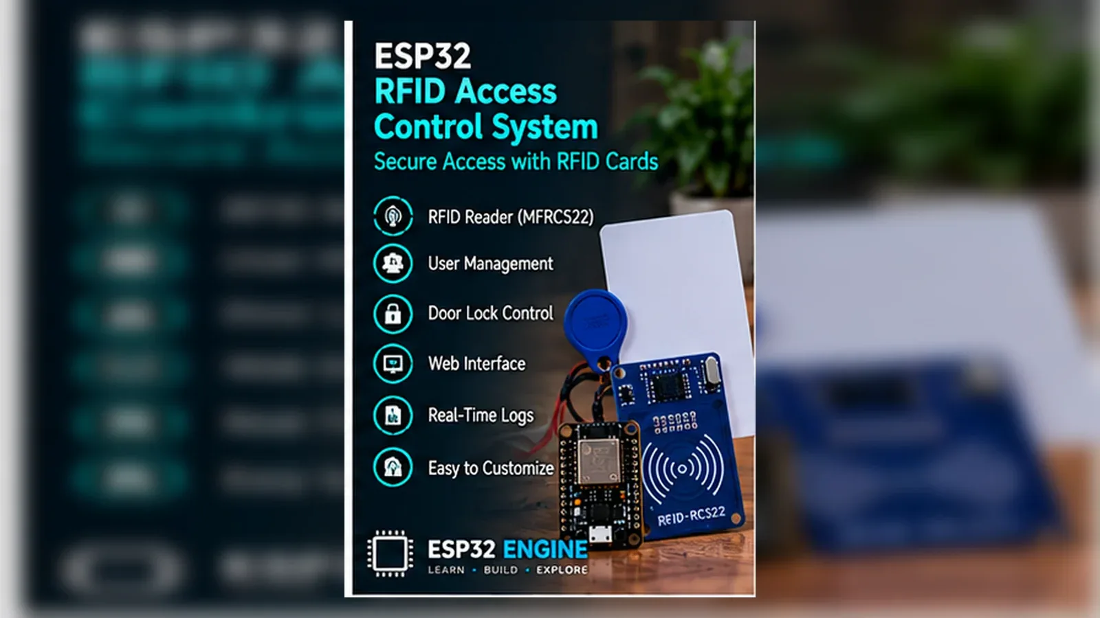
Build Your RFID Access Control System
The Story
ESP32 RFID Access Control System reads MFRC522 card UID bytes over SPI, compares each scan with an allowed UID in the sketch, and pulses the GPIO26 access output only when the card matches.
The important lesson is not only the finished access control system. You learn to verify the RFID reader on Serial Monitor before attaching the relay or servo output, and to treat hobby RFID cards as identifiers for a learning prototype, not tamper-resistant security.
Explain Like I'm 12
Think of the ESP32 as the brain. The MFRC522 reader checks the card ID. The relay or servo output is the small action the brain takes when the card is approved.
Safety Standards
- Unplug USB before changing jumper wires. Recheck 3.3 V, 5 V, and GND before reconnecting power.
- Do not power motors, pumps, LED strips, or servos from the ESP32 3.3 V pin. Use a suitable external supply and common ground.
- Breadboards are for low-current prototypes. Move high-current or unattended builds to proper terminals, enclosure, strain relief, and fusing.
- Relay and mains-voltage projects require isolation, correct relay ratings, enclosed wiring, and qualified adult supervision.
- Motors and servos can reset the ESP32 when they draw surge current. Use a separate motor supply, driver module, and flyback protection where needed.
What You Will Build
A working educational RFID access control prototype with an ESP32, an MFRC522/RC522 reader, SS on GPIO5, RST on GPIO22, a relay or servo output on GPIO26, Serial Monitor messages for access granted and access denied, and clear limits so it is not mistaken for certified door security.
Learning Objectives
- Wire and test the MFRC522 RFID reader before connecting the rest of the circuit.
- Map each signal to a named ESP32 GPIO and keep the code constants readable.
- Control relay or servo lock output from a clear approved-card decision.
- Use Serial Monitor as an engineering tool, not only as a success message.
- Identify power, wiring, and timing faults using a repeatable test checklist.
Components List
- ESP32 DevKit boardMain controller
- MFRC522 / RC522 RFID reader3.3 V RFID card reader using SPI
- Relay module or servo lock outputLow-voltage demonstration output on GPIO26
- Breadboard and jumper wiresPrototype wiring
- USB data cableProgramming and testing
Bill of Materials
| Part | Qty | Estimated Cost | Notes |
|---|---|---|---|
| ESP32 DevKit | 1 | $6-$10 | USB board |
| MFRC522 / RC522 RFID reader | 1 | $2-$10 | 3.3 V SPI reader; verify module labels |
| Relay module or servo lock output | 1 | $3-$12 | Use low-voltage test hardware only |
| Breadboard and wires | 1 set | $3-$5 | Prototype wiring |
Wiring
Wire the MFRC522 RFID reader first, verify card UID reads in Serial Monitor, then connect the GPIO26 relay or servo output. Treat this as a low-voltage access-control lesson, not a certified lock system.
-
1
Unplug USB before placing modules on the breadboard.
-
2
Connect the MFRC522 RFID reader VCC to 3.3 V unless your exact module documentation says otherwise.
-
3
Connect MFRC522 GND to ESP32 GND.
-
4
Connect MFRC522 SS/SDA to GPIO5 and RST to GPIO22 to match the sketch constants.
-
5
Connect the remaining MFRC522 SPI lines to the ESP32 board SPI pins used by SPI.begin().
-
6
Connect the relay module input or servo signal to GPIO26 and share ground with the ESP32.
-
7
Power any actuator from suitable low-voltage hardware; do not power a lock, relay coil, or servo directly from an ESP32 GPIO.
GPIO Mapping
| Signal | ESP32 Pin | Direction | Notes |
|---|---|---|---|
| MFRC522 VCC | 3.3 V | Power | MFRC522/RC522 readers are normally 3.3 V logic devices. |
| MFRC522 GND | GND | Ground | Shared ground with ESP32. |
| MFRC522 SS/SDA | GPIO5 | Output | Chip-select pin defined as SS_PIN in the sketch. |
| MFRC522 RST | GPIO22 | Output | Reset pin defined as RST_PIN in the sketch. |
| MFRC522 SPI bus | Board SPI pins | I/O | SPI.begin() uses the ESP32 board/library SPI setup. |
| Relay or servo lock output | GPIO26 | Output | Control signal only; use a relay module, servo supply, or driver appropriate to the actuator. |
| Status LED | GPIO2 | Output | Optional debug indicator |
| Serial Monitor | USB | Debug | 115200 baud |
Circuit Explanation
The circuit is split into an RFID input side and an actuator output side. The MFRC522 reader communicates over SPI and uses GPIO5 for SS and GPIO22 for reset in this sketch. GPIO26 controls the output module; it does not power the actuator directly.
Engineering Explanation
A reliable access control system is built in layers. First prove the input, then prove the output, then join them with simple state logic. This prevents a common beginner problem where the robot, lock, or automation fails and every wire looks suspicious at the same time.
Code
Copy into Arduino IDE. Install any libraries noted in the component guides first.
#include <SPI.h>
#include <MFRC522.h>

#define SS_PIN 5
#define RST_PIN 22
#define RELAY_PIN 26

MFRC522 rfid(SS_PIN, RST_PIN);
byte allowedUid[] = {0xDE, 0xAD, 0xBE, 0xEF};

bool uidMatches() {
  if (rfid.uid.size != sizeof(allowedUid)) return false;
  for (byte i = 0; i < rfid.uid.size; i++) {
    if (rfid.uid.uidByte[i] != allowedUid[i]) return false;
  }
  return true;
}

void setup() {
  Serial.begin(115200);
  pinMode(RELAY_PIN, OUTPUT);
  digitalWrite(RELAY_PIN, LOW);
  SPI.begin();
  rfid.PCD_Init();
  Serial.println("Scan RFID card");
}

void loop() {
  if (!rfid.PICC_IsNewCardPresent() || !rfid.PICC_ReadCardSerial()) return;
  bool allowed = uidMatches();
  Serial.println(allowed ? "Access granted" : "Access denied");
  digitalWrite(RELAY_PIN, allowed ? HIGH : LOW);
  delay(1500);
  digitalWrite(RELAY_PIN, LOW);
  rfid.PICC_HaltA();
}
Code Explanation
The example defines SS_PIN as GPIO5, RST_PIN as GPIO22, and RELAY_PIN as GPIO26. It compares the scanned UID bytes with allowedUid, prints "Access granted" or "Access denied", and pulses the output only for an approved card.
Expected Output
Serial Monitor should print "Scan RFID card" after boot. A UID that matches allowedUid should print "Access granted" and activate GPIO26 for about 1.5 seconds. Any other card should print "Access denied" and leave the output inactive.
Troubleshooting
- MFRC522 RFID reader never detects a card Check 3.3 V power, GND, SS on GPIO5, RST on GPIO22, SPI wiring, and card position over the antenna.
- Every card is denied Print the scanned UID bytes first, then replace allowedUid with the exact UID from your own card.
- Relay or servo output does not switch Test GPIO26 with a simple output sketch, then test the relay module or servo with its own safe low-voltage supply.
- ESP32 resets under load Use a separate supply for motors, pumps, or locks and keep only control signals connected to ESP32.
- Behavior is reversed Your module may be active LOW; invert the output logic after confirming with Serial Monitor.
Common Mistakes
- Testing input and output for the first time together.
- Using a GPIO pin that does not match the code constant.
- Expecting an ESP32 GPIO to power a motor, pump, or lock directly.
- Forgetting the shared ground between modules.
Testing Checklist
- ESP32 appears on the correct port and accepts a basic blink upload.
- Ground is shared between every module that exchanges signals with the ESP32.
- Each GPIO in the code matches the wire connected on the breadboard.
- Serial Monitor prints startup text at 115200 baud.
- A scanned card prints either Access granted or Access denied.
- The relay or servo lock output changes only for an approved UID.
- The circuit still behaves correctly after power is removed and restored.
Upgrade Ideas
- Add OLED status feedback.
- Add Wi-Fi dashboard or mobile alerts.
- Store event history in flash or a cloud service.
- Add calibration settings instead of hard-coded thresholds.
Real-World Applications
- Classroom access control system trainer
- STEM lab demonstration
- Home automation prototype
- Engineering debugging practice
- IoT portfolio project
Downloads
- ESP32 RFID Access Control System Arduino sketchUse the code section as the downloadable source until file downloads are published.
- Wiring checklistMatch the GPIO table and wiring steps before powering the circuit.
- Troubleshooting worksheetRecord symptoms, Serial output, voltage checks, and fixes.
FAQs
Why does my MFRC522 RFID reader reading look wrong?
Check SPI wiring, reader power, ground, and card distance. MFRC522 modules are sensitive to loose wires and poor antenna placement.
Why does relay or servo lock output not respond?
Check the ground connection first. Then confirm the output pin, power supply capacity, and whether the output module uses active HIGH or active LOW logic.
Should I use this as a real door access system?
No. This is a low-voltage learning prototype. Hobby RFID tags can be cloned or bypassed, and real access systems need proper mechanical security, fail-safe design, logging, enclosure, and installation review.
Review, Testing, and References
Author: Abdul Mubeen and the ESP32 Engine editorial team. Last updated: 2026-08-23. Reviewed: wiring logic, Arduino code structure, beginner safety, and learning sequence.
Educational level: Intermediate. Estimated completion time: 90-150 min. This project is for learning and prototyping; production or unattended hardware needs additional engineering review.
Project Complete!
You built a real access control system and learned how to connect sensing, decision logic, and output control in one ESP32 project.
- Wire and test MFRC522 RFID reader
- Control relay or servo lock output from ESP32
- Debug hardware with Serial Monitor
- Improve the project safely