
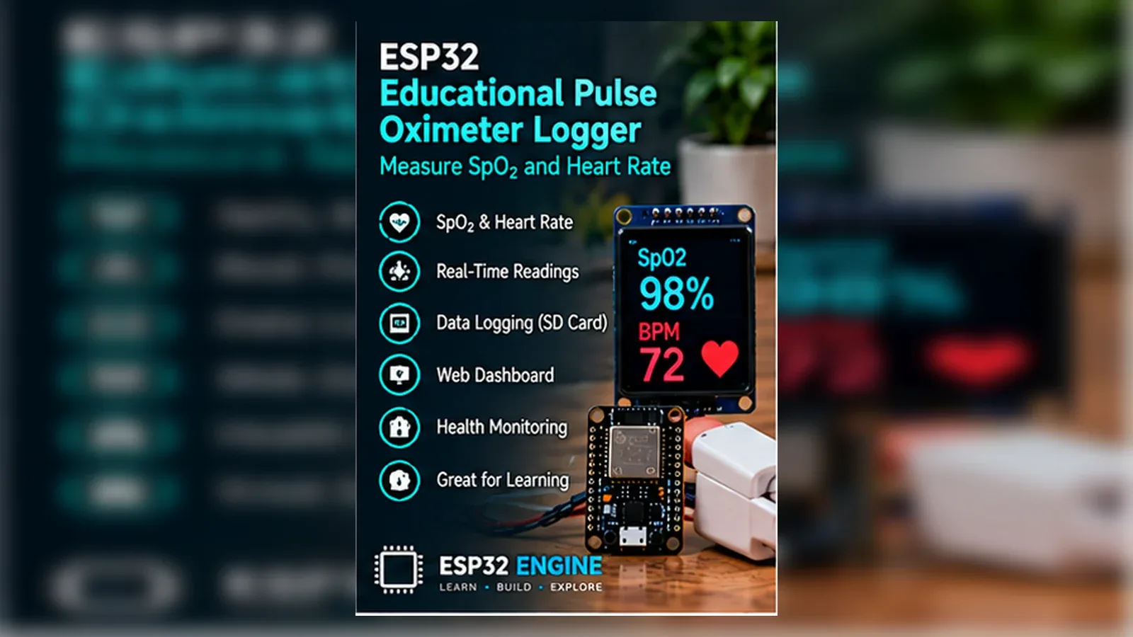
Build an Educational Pulse Oximeter Logger
The Story
A pulse oximeter looks simple from the outside, but the electronics are really watching tiny changes in reflected red and infrared light. This Golden version keeps the project honest: it is an educational signal logger, not a health monitor, diagnosis tool, emergency device, or clinical instrument.
Explain Like I'm 12
The MAX30102 shines red and infrared light into a fingertip and measures how much light comes back. The ESP32 watches the changing numbers and prints estimated values so you can learn about optical sensing. If there is no finger, the sketch refuses to show stale estimates.
Learning Support
- Recommended ageAges 14+
- Adult supervisionRequired for shared classroom use and for understanding the medical boundary.
- Classroom useUse this as an optics and signal-processing lesson, not as a health screening station.
- Parent promptAsk why an estimated classroom sensor reading is not the same as a clinical measurement.
- Screen-free activityDraw how red and infrared light pass through a fingertip and scatter back to the sensor.
- Next challengeLog raw red/IR values to CSV and analyze motion artifacts offline.
- Skills practiced
- I2C wiring
- Optical sensor setup
- Validity checks
- Medical-safety wording
- Learning outcomes
- Wire MAX30102 SDA to GPIO21 and SCL to GPIO22.
- Suppress stale readings when no finger is detected.
- Label BPM and SpO2 as estimated educational values.
- Explain why the project is not a medical device.
- Mini experiments
- Watch IR values change when a finger is placed on the sensor.
- Compare stable and moving-finger readings.
- Adjust the finger threshold only after recording idle sensor values.
Safety Standards
- Unplug USB before changing jumper wires. Recheck 3.3 V, 5 V, and GND before reconnecting power.
- Do not power motors, pumps, LED strips, or servos from the ESP32 3.3 V pin. Use a suitable external supply and common ground.
- Breadboards are for low-current prototypes. Move high-current or unattended builds to proper terminals, enclosure, strain relief, and fusing.
What You Will Build
A MAX30102 I2C logger that prints estimated BPM, estimated SpO2, and raw red/IR values while suppressing no-finger readings.
Components List
- ESP32 DevKit boardUse 3.3 V logic and I2C on GPIO21/GPIO22.
- MAX30102 breakout moduleOptical red/IR sensor module; this project uses educational estimates only.
- Breadboard and jumper wiresShort, firm connections reduce I2C and power problems.
- USB data cableNeeded for upload and Serial Monitor.
- Cleaning wipes for shared demosClean the finger-contact area between users.
Bill of Materials
| Part | Qty | Estimated Cost | Notes |
|---|---|---|---|
| ESP32 DevKit board | 1 | Varies | Use 3.3 V logic and I2C on GPIO21/GPIO22. |
| MAX30102 breakout module | 1 | Varies | Optical red/IR sensor module; this project uses educational estimates only. |
| Breadboard and jumper wires | 1 | Varies | Short, firm connections reduce I2C and power problems. |
| USB data cable | 1 | Varies | Needed for upload and Serial Monitor. |
| Cleaning wipes for shared demos | 1 | Varies | Clean the finger-contact area between users. |
Wiring
The MAX30102 uses I2C. SDA is GPIO21, SCL is GPIO22, VCC is 3.3 V, and GND is common ground.
-
1
Unplug USB before placing or moving jumper wires.
-
2
Connect MAX30102 VCC to ESP32 3V3.
-
3
Connect MAX30102 GND to ESP32 GND.
-
4
Connect MAX30102 SDA to GPIO21.
-
5
Connect MAX30102 SCL to GPIO22.
-
6
Plug in USB, upload the sketch, and open Serial Monitor at 115200 baud.
GPIO Mapping
| Signal | ESP32 Pin | Direction | Notes |
|---|---|---|---|
| MAX30102 SDA | GPIO21 | I2C data | Default ESP32 I2C SDA in this sketch. |
| MAX30102 SCL | GPIO22 | I2C clock | Default ESP32 I2C SCL in this sketch. |
Circuit Explanation
The MAX30102 breakout handles the optical sensor front end and communicates with the ESP32 over I2C.
Engineering Explanation
The finger threshold is a practical validity gate for this educational setup. Estimated BPM and SpO2 are heuristic classroom outputs and are not calibrated clinical measurements.
Libraries
- SparkFun MAX3010x libraryProvides MAX30105/MAX30102 sensor access and heartRate helper.
Code
Copy into Arduino IDE. Install any libraries noted in the component guides first.
// ESP32 MAX30102 educational pulse-wave estimate logger
// Not a medical device. Not for diagnosis, treatment, or emergency use.
#include <Wire.h>
#include "MAX30105.h"
#include "heartRate.h"

MAX30105 sensor;

const long FINGER_IR_THRESHOLD = 50000;
const byte RATE_SIZE = 4;
byte rates[RATE_SIZE];
byte rateSpot = 0;
long lastBeat = 0;
float estimatedBpm = 0;

void setup() {
  Serial.begin(115200);
  Wire.begin(21, 22);

  if (!sensor.begin(Wire, I2C_SPEED_STANDARD)) {
    Serial.println("MAX30102 not found. Check SDA GPIO21, SCL GPIO22, 3.3 V, and GND.");
    while (true) delay(10);
  }

  sensor.setup();
  sensor.setPulseAmplitudeRed(0x1F);
  sensor.setPulseAmplitudeIR(0x1F);
  Serial.println("Educational MAX30102 logger ready - estimated values only, not medical data.");
}

void loop() {
  long irValue = sensor.getIR();
  long redValue = sensor.getRed();

  if (irValue < FINGER_IR_THRESHOLD) {
    estimatedBpm = 0;
    Serial.println("No finger detected - estimated BPM/SpO2 suppressed (educational only).");
    delay(500);
    return;
  }

  if (checkForBeat(irValue)) {
    long now = millis();
    long delta = now - lastBeat;
    lastBeat = now;

    float bpm = 60.0 / (delta / 1000.0);
    if (bpm > 40 && bpm < 180) {
      rates[rateSpot++] = (byte)bpm;
      rateSpot %= RATE_SIZE;
      int total = 0;
      int count = 0;
      for (byte i = 0; i < RATE_SIZE; i++) {
        if (rates[i] > 0) {
          total += rates[i];
          count++;
        }
      }
      if (count > 0) estimatedBpm = (float)total / count;
    }
  }

  float ratio = redValue > 0 ? (float)irValue / (float)redValue : 0.0;
  float estimatedSpo2 = constrain(104.0 - 17.0 * ratio, 70.0, 100.0);

  Serial.printf("Estimated BPM: ~%.0f - educational only | Estimated SpO2: ~%.0f%% - educational only | IR: %ld Red: %ld\n",
                estimatedBpm, estimatedSpo2, irValue, redValue);
  delay(100);
}
Code Explanation
The sketch initializes I2C on GPIO21/GPIO22, suppresses estimates below the IR finger threshold, averages plausible beat intervals, and prints every value as estimated educational data.
Expected Output
With no finger, Serial Monitor reports that estimates are suppressed. With a steady finger, it prints lines such as Estimated BPM and Estimated SpO2 along with raw IR and red counts; these are learning values only.
Troubleshooting
- MAX30102 not found Check 3.3 V, GND, SDA GPIO21, SCL GPIO22, and library installation.
- No finger detected all the time Check finger placement and record idle IR values before changing the threshold.
- Estimated BPM jumps around Hold still, block bright ambient light, and remember the value is not clinical.
Common Mistakes
- Treating estimated values as medical readings.
- Powering a 3.3 V-only breakout from 5 V.
- Swapping SDA and SCL.
- Showing old readings after the finger is removed.
Testing Checklist
- Confirm I2C detection.
- Confirm no-finger suppression.
- Confirm labels say Estimated.
- Clean shared sensor surfaces.
Engineering Tips
- Keep I2C wires short.
- Use raw IR/red data for debugging.
- Never publish health claims from this sketch.
Upgrade Ideas
- Save raw red/IR samples to CSV.
- Add an OLED that repeats the educational-only warning.
- Graph raw values in a local dashboard without medical claims.
Real-World Applications
- Optical sensor classroom demo
- Signal-validity lesson
- Bioinstrumentation ethics discussion
FAQs
Is this a medical pulse oximeter?
No. It is only an educational optical sensor logger.
Can I use the estimated SpO2 value for health decisions?
No. Do not use it for diagnosis, treatment, emergency use, or reassurance.
Review, Testing, and References
Author: Abdul Mubeen and the ESP32 Engine editorial team. Last updated: 2026-07-10. Reviewed: wiring logic, Arduino code structure, beginner safety, and learning sequence.
Educational level: Advanced. Estimated completion time: 60-75 min. This project is for learning and prototyping; production or unattended hardware needs additional engineering review.
Project Complete!
You built an honest educational optical-sensing logger. The wiring, code, output labels, safety notes, and troubleshooting all agree that the ESP32 reads MAX30102 signals for learning only.
- I2C sensor wiring
- Finger-presence validation
- Estimated-value labeling
- Safety-bounded troubleshooting