
The Story
A room sensor is a useful first step toward a climate monitor. The DHT22 gives your ESP32 two simple readings, but a reliable build depends on identifying the right pins and letting the sensor work at its own pace.
Background reading
Build a dependable ESP32 temperature-and-humidity reader with the DHT22. Identify the sensor pins, wire a bare sensor or module safely, install the Arduino library, and understand the complete sketch before extending it.
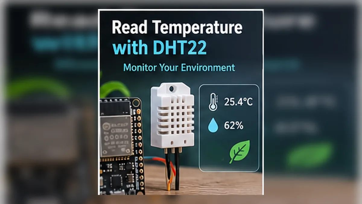
A room sensor is a useful first step toward a climate monitor. The DHT22 gives your ESP32 two simple readings, but a reliable build depends on identifying the right pins and letting the sensor work at its own pace.
The DHT22 is a small digital sensor that reports how warm and humid the air is. The ESP32 asks it over one data wire, then prints the two readings on your computer.
Author: Abdul Mubeen and the ESP32 Engine editorial team. Last updated: 2026-10-01. Reviewed: educational accuracy and beginner safety. Level: Beginner. Estimated time: 12 min read.
This guide is written for learning and bench prototyping. Check the testing notes before adapting the circuit to different boards, batteries, relays, motors, or outdoor hardware.
The DHT22 is a digital sensor for air temperature and relative humidity. Its controller sends the measurements as a timed digital signal on one bidirectional data line. The ESP32 library decodes that signal; this is not an analog sensor and it does not use the I2C bus.
A DHT22 does not measure barometric pressure, air quality, or altitude. It is useful for basic room, greenhouse, or classroom monitoring, but its update rate is slow and readings depend on placement and the sensor's documented operating conditions. Do not treat it as a precision instrument or as a fast feedback sensor. The DHT22 component reference has concise component details; this guide focuses on wiring and using it with an ESP32.
DHT22 and AM2302 are commonly used names for this sensor family. You may find a bare four-pin sensor, a wired probe, or a small three-pin breakout module. The sensing function is similar, but the package, pin order, connector labels, power circuitry, and presence of a pull-up resistor can differ. Use the datasheet and markings for the exact part instead of assuming every board is wired the same way.
A common bare DHT22 package has four pins: VDD/VCC, DATA (sometimes marked SDA), NC (no connection), and GND. On the usual front view with the grille toward you and pins pointing down, those pins are arranged left to right in that order. Check the datasheet for your exact sensor before wiring because package drawings and clone markings can differ.
Three-pin breakout boards typically label the connections with some combination of VCC/+ , DATA/S/OUT, and GND/-. A module's physical pin order is board-specific; follow its silkscreen or wiring diagram rather than copying the bare sensor's left-to-right order. The DHT22 wiring diagram shows one example connection.
| Sensor connection | ESP32 example | What to check |
|---|---|---|
| VDD, VCC, or + | 3V3 | Use a bare sensor or module documented to operate from 3.3 V for this direct-connection example. |
| DATA, SDA, S, OUT | GPIO4 | The code uses GPIO4 on a common original ESP32 DevKit; change DHT_PIN if your board or wiring uses another suitable GPIO. |
| GND or - | GND | Sensor and ESP32 need a common ground. |
| NC on a bare four-pin sensor | Leave unconnected | NC means no connection. Do not use this pin as a second data line. |
DHT_PIN.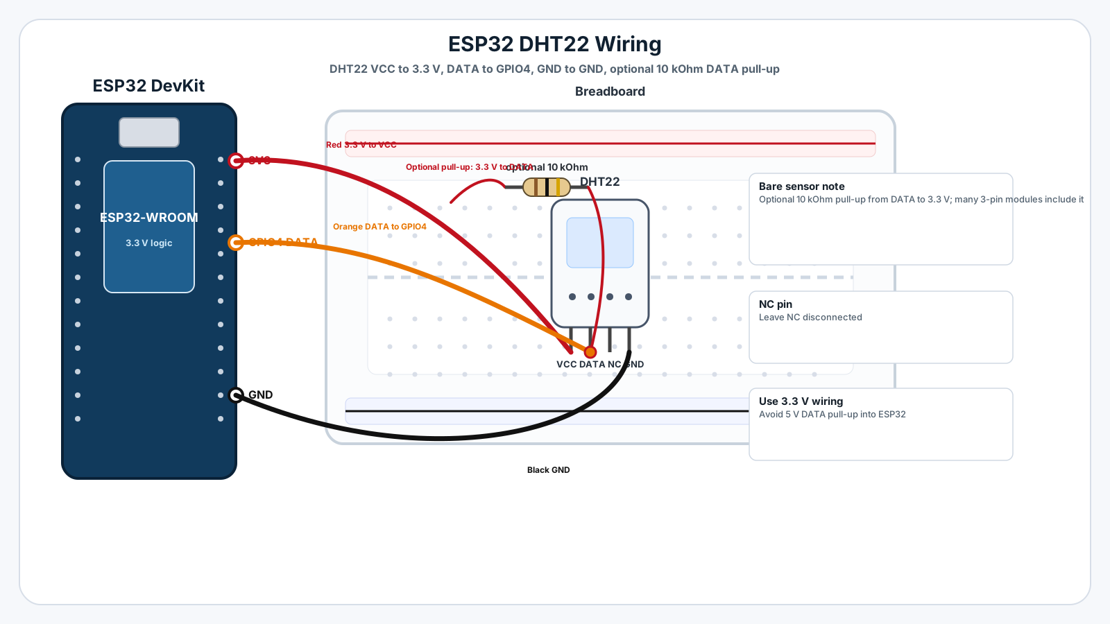
The DHT22's one-wire data line is released between signals, so it needs a pull-up to return to a HIGH level. A bare sensor normally needs an external resistor between DATA and its supply. The manufacturer shows 5.1 kΩ as a typical pull-up for short connections; Adafruit's example uses 10 kΩ. For this ESP32 example, connect the pull-up to 3.3 V, not 5 V.
Many three-pin modules include a pull-up on the small board, but this is not guaranteed. Check the module documentation or circuit. If a pull-up is already present, an additional resistor may be unnecessary. Never allow a 5 V pull-up to drive an ESP32 GPIO directly. The exact bare-sensor electrical limits and timing are in the manufacturer's AM2302 technical manual.
DHT_PIN to the GPIO connected to DATA and keep DHT_TYPE set to DHT22.The library and its current dependencies are documented in the Adafruit DHT sensor library repository. Avoid installing multiple libraries that provide a different DHT.h header; that can cause compile errors or inconsistent behavior.
    #include <DHT.h>

    // Example for a common original ESP32 DevKit. Match this to your wiring.
    const uint8_t DHT_PIN = 4;
    #define DHT_TYPE DHT22

    DHT dht(DHT_PIN, DHT_TYPE);

    void setup() {
      Serial.begin(115200);
      dht.begin();

      // Let the sensor settle before the first measurement.
      delay(2100);
      Serial.println("ESP32 DHT22 reader ready");
    }

    void loop() {
      const float humidity = dht.readHumidity();
      const float temperatureC = dht.readTemperature();

      if (isnan(humidity) || isnan(temperatureC)) {
        Serial.println("Failed to read from DHT sensor; check wiring and settings.");
      } else {
        Serial.print("Temperature: ");
        Serial.print(temperatureC, 1);
        Serial.println(" °C");

        Serial.print("Humidity: ");
        Serial.print(humidity, 1);
        Serial.println(" %");
      }

      // The DHT22 should not be sampled more often than every 2 seconds.
      delay(2000);
}DHT_PIN: the ESP32 GPIO connected to the sensor's DATA line. If you change the wire, update this constant too.DHT_TYPE: tells the library to use DHT22 timing rather than another DHT model.dht.begin(): initializes the library for the selected sensor and pin.readTemperature(): returns Celsius by default. readTemperature(true) requests Fahrenheit if you need it.readHumidity(): returns relative humidity as a percentage.isnan(): detects an invalid reading so the sketch can report an error instead of printing a misleading number.Choose 115200 baud in Serial Monitor to match Serial.begin(115200). A working sensor should print output in this general format; your room's values will differ:
ESP32 DHT22 reader ready
DHT22 and AM2302 are commonly used names for the same temperature-and-humidity sensor family. Physical packaging and breakout boards vary, so check the markings and documentation for the exact part you have.
A bare four-pin sensor needs a pull-up on DATA. Many three-pin modules include one, but module designs vary; check its documentation or circuit before adding another resistor.
This example uses GPIO4 on a common original ESP32 DevKit. GPIO availability varies across ESP32 boards, so confirm the pinout for your board and update DHT_PIN to match the wire.
NaN means the library did not get a valid reading. Check the selected GPIO, VCC and GND, the DATA pull-up, the DHTTYPE setting, library installation, and the interval between reads.
Allow at least two seconds between measurements. The sensor updates slowly, and requesting readings more frequently can return an old value or cause a failed read.
No. It measures temperature and relative humidity. For pressure readings or pressure-based altitude estimates, use a sensor such as the BME280 instead.
Start with the 3.3 V wiring, a suitable DATA pull-up, and a two-second sampling interval. Once the Serial Monitor readings are stable, continue to the guided DHT22 mission or adapt the sensor for a climate-control or MQTT project. Use a different sensor when your project needs pressure, faster updates, or tighter documented performance.